(855) 676-0881

Commercial Door Operator Not Responding: Control and Limit Diagnosis


Published: Nov 9, 2026

When a commercial door operator stops responding, facility operations grind to a sudden halt. A jammed bay door or unresponsive operator head can cost a business between $500 and $2,000 per hour in logistics delays, labor bottlenecks, and compromised building security.

Field diagnostic data reveals that roughly 80% of non-responsive commercial operator service calls trace back to four primary root causes: safety entrapment lockout, mechanical binding triggering motor protections, control voltage drops, or active auxiliary safety interlocks. Resolving these issues requires a methodical evaluation of control power, limit switches, and logic board telemetry.
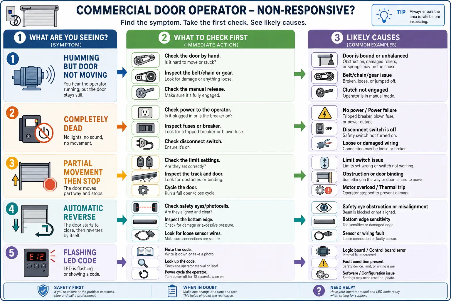
Emergency Quick-Start: Non-Responsive Operator Triage Matrix


Before taking a multimeter to the control panel, systematically identify your operator’s physical symptoms against this initial diagnostic matrix to narrow down potential failure points.

This symptom-to-cause matrix visually clarifies initial troubleshooting steps for commercial door operators that are not responding, empowering facility managers and technicians to identify probable root causes quickly.

Phase 1: Electrical System & Control Power Diagnosis


Diagnosing a non-responsive operator begins at the incoming power terminal block and secondary control transformer.

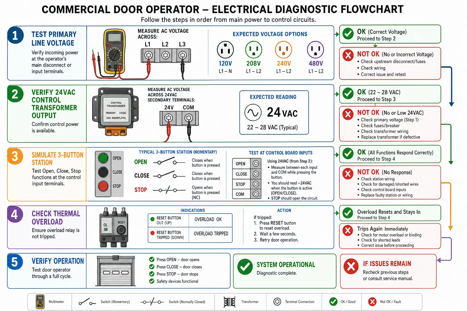
This flowchart breaks down complex electrical system diagnostics into clear, logical steps, showing how to systematically verify line power, control voltages, and button stations to isolate faults.

First, verify primary line voltage ($120text{V}$, $208text{V}$, $240text{V}$, or $480text{V}$) across incoming power terminals $L1, L2,$ and $L3$. A single dropped leg on a three-phase system causes motor humming and trips the internal thermal overload switch. Next, check the secondary output of the step-down control transformer. It should deliver a steady $24text{VAC}$ to the logic board terminals. A blown transformer fuse or shorted secondary winding cuts power to all control stations completely.

Next, examine the three-button control station (Open, Close, Stop). Commercial control circuits rely on a Normally Closed (N.C.) Stop button loop. If the Stop button microswitch sticks open or suffers wire failure, the circuit breaks, locking out all command inputs. If immediate site power issues are ruled out, fast dispatch via emergency commercial door repair prevents prolonged facility exposure.

Phase 2: Interlock & Safety Circuit Lockout Diagnosis


Under safety standard UL 325, commercial operators mandate continuous monitoring of primary entrapment devices. If a safety device fails, wiring breaks, or optical lenses become misaligned, the logic board defaults to a safety lockout or constant-pressure close override.

Beyond photo-eyes, physical interlocks are common hidden triggers:

  • Auxiliary Chain Hoist Interlocks: On manual override jackshaft operators, pulling the hoist chain opens an internal microswitch that cuts 24V control power to prevent electrical motor activation during manual hand-chain operation.
  • Pass-Door Interlocks: Pedestrian doors embedded within rolling doors feature magnetic or mechanical switches. If unlatched, the control board disables all movement.

For comprehensive hardware evaluations, linking diagnostic steps to full system reviews such as an industrial door energy efficiency assessment ensures both operational reliability and structural integrity.

Phase 3: Limit Switch Assembly & Encoder Calibration


When an operator runs briefly but stops short or over-travels into the header, limit system failure is usually responsible.

  • Mechanical Rotary Limits: These assemblies use traveling limit nuts on a threaded drive shaft that contact Open or Close microswitches. Inspect for sheared drive gears, loose retaining bracket plates, or worn microswitch dry contacts using a multimeter continuity setting.
  • Digital Positioning Encoders: Modern logic platforms (e.g., LiftMaster Logic 5, Genie IntelliG) use optical encoders or Hall-effect sensors for millimeter-precise tracking. Debris on the encoder wheel or a loose harness causes the board to lose position memory, triggering an immediate safety stop.

If your facility utilizes specialized entrance systems, standard automatic door repair techniques apply to verifying optical safety loops and limit positions.

Phase 4: Logic Board Diagnostics & LED Error Code Master Lookup


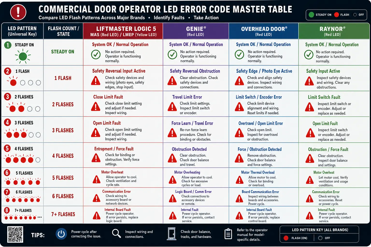
Modern commercial logic control boards provide diagnostic telemetry via LED flash patterns.

This multi-brand LED flash code master table helps technicians and facility staff quickly decode operator logic board errors by pattern recognition, improving troubleshooting speed and accuracy.

On LiftMaster Logic 5 boards, Maintenance Alert System (MAS) flashes indicate:

  • MAS 2 Flashes: Mechanical binding / clutch slippage detected via RPM sensor.
  • MAS 4 Flashes: RPM sensor connection error or board optical sensor fault.
  • MAS 8 Flashes: Line voltage brownout or control board power interruption.

For sliding architectural overhead gates or entryways, integrated automatic sliding door repair protocols follow similar diagnostic resets: power cycle the board, re-align monitored photo-eyes (LMEP solid light), and verify limit travel parameters.

MOFU Decision Framework: In-House Repair vs. Professional Dispatch


Evaluating whether to complete repairs internally or call in certified commercial technicians comes down to cost, safety risk, and equipment complexity:

  • In-House Repair (Part Swap): Replacing a $40–$100 mechanical limit microswitch, adjusting limit nuts, or clearing photo-eye obstructions is well within the scope of internal facility maintenance teams.
  • Logic Board Replacement: Swapping a corrupted logic board costs $150–$400 in parts. Ensure wiring pinouts match exactly to preserve UL 325 safety settings.
  • Professional Dispatch: If line voltage drops occur across main power feeders, internal motor windings show shorted continuity, or high-tension counterbalance springs have lost torque, professional dispatch ($200–$500 average service call) is essential to avoid severe safety hazards and costly mechanical downtime.

Frequently Asked Questions


Why does my commercial door only close when I hold down the close button continuously?

This behavior indicates a failure in your UL 325 monitored entrapment protection system. If photo-eyes are misaligned, dirty, damaged, or experiencing wiring continuity faults, the board defaults to constant-pressure manual override mode for safety.

How do I reset a commercial logic board after clearing a limit or mechanical fault?

Power down the operator for 30 seconds to clear temporary memory buffers. Upon restoring power, verify that the diagnostic LED shifts from an error flash sequence to steady standby status, then perform a complete open-and-close cycle to re-calibrate limit positions.

What should I check if the motor hums but the door does not move at all?

Check for a dropped electrical phase on 3-phase systems, an engaged auxiliary chain hoist interlock switch, a tripped manual motor overload reset button, or a completely bound mechanical door spring shaft.