Before calling out a technician, facility managers can perform this systematic diagnostic protocol to identify if your automatic door sensor not working is due to a simple environmental factor or a hardware failure.
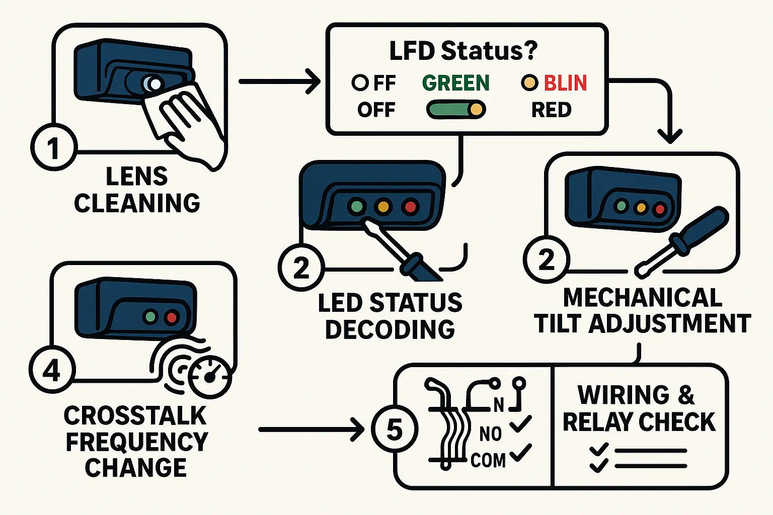
The Lens Inspection (Cleaning Protocol)
Over time, dust, road salt, rain spots, and exhaust film coat the polycarbonate lens of header-mount sensors. This buildup scatters the infrared beams, leading to a false “clear” state or triggering a constant safety lockout. Wipe the sensor lens gently with a clean, damp microfiber cloth. Avoid harsh chemical cleaners that can cloud the plastic.
The LED Status Code Decoder
Observe the LED indicator on your sensor header (such as a BEA Bodyguard, SDC AUTO-IR, or Optex OA-Presence):
- Solid Green: Standby mode (no detection).
- Solid Red: Active presence detection (the door should remain open).
- Flashing Red/Orange: Internal error or signal crosstalk.
Mechanical Tilt Adjustment
If your LED remains green when someone stands in the door path, the infrared curtain may be tilted too far outward, creating a “dead zone” directly in the door track. Using the manual adjustment screws on the sensor chassis, adjust the angle of the physical module to shift the pattern closer to the threshold.
Vestibule Crosstalk Elimination
If you have adjacent automatic doors, their active infrared frequencies may interfere with one another. To resolve this “crosstalk,” locate the internal dip switches on the sensor board and change the frequency channel on one of the units according to the manufacturer’s schematic.
Wiring & Relay Failsafe Check
Ensure the sensor’s wiring harness is seated firmly in the door controller. If the wiring is loose or the contacts are corroded, the “Normally Closed” (NC) or “Normally Open” (NO) safety loop may fail, preventing the controller from receiving the safety override signal.